I am starting this thread more as an example of how I can undertake projects with no knowledge of what I am doing and how these projects usually never get finished! Anyway, I will have fun and will put some pics up tonight.

I am starting this thread more as an example of how I can undertake projects with no knowledge of what I am doing and how these projects usually never get finished! Anyway, I will have fun and will put some pics up tonight.

I had to ask Absinth how to get the second hand off so all credit goes to him for getting me past point A! Thanks Absinth.
The long thin silver bit with the peg on it what the coil activates to make the clock go, and this where the humming comes from I am guessing.
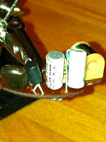
The green thing is the coil, the tall grey cylinders are two of the capacitors and the flat black thing is also a capacitor(which is meant to be green). The other skinny dudes are diodes. The other round black thing is a transistor.

I am looking forward to seeing if changing out the 3 resistors, 3 capacitors and transistor fix it. Did you get a new coil as well as these can be a problem if they are overheated or burnt out. I have all the bits, just haven't had the time to do it.
Only thing is, I swapped a working clocks PC board into a non working clock and it didn't fix it.... the PC board components may be on their way out but still run a slightly weaker clock mechanism.
The clock mechanisms seem to work fine so it has to be the electronic part that fails.
4/75 HJ XX7 Sandman Panelvan ... Persian Sand currently restoring
7/76 HX Monaro 4dr 308 4sp... Absinth Yellow and rusty as hell.. SOLD
3/77 HX Sandman Panelvan ... Absinth Yellow and rusty as hell .. SOLD


Have a look here. There are also links at the bottom too.
http://holdenpaedia.oldholden.com/Clocks

Absinth, I did not get a coil and it looks as though it would be the most difficult bit on the board to replace, so that is a last resort at this stage. I replaced the two larger caps last night and will get back onto it when the rest of the bits arrive.
Replacing the board with one that works and still having no luck does not make me too confident, but lets hope.
Thanks for the links Byron, I reckon that a RAAF tech and me would be close to the same skill levels...... not

OK. Replaced the 3 Capacitors last night. Put it back together and wired it up to a uhf base station transfromer........ and the tuning fork now hums away but it wont drive the the gear for some reason. Will try a few more things and see how I go.
They are called a tuning fork mechanism. They were designed in the 40's by an English clock making company. JECO of Japan built them and they supplied Smiths with the same mechanism for their clocks.
The tuning fork vibrates when the coil is energised which then drives the clock. This is why the clock hums and is also why the clocks do not tick like a conventional clock.
So our true blue Holdens are running a Japanese clock and strangely it is the most unreliable gauge in the dash!
When you pull the adjusting knob it gives the mechanism a helping hand to start, so if you have had the battery out for a while its not a bad idea to give the clock a flick with the adjuster to get it started when you hook it back up.
Last edited by wbute; 17-04-2011 at 07:02 AM.


I don't have any gears but you should be able to get the capacitors. I got some from jaycar and some from a TV repair place.

How about a picture of the board. I forgot to take one and now I can't remember where the wires solder up...
After years of owning heaps of cars with these dashes and fitting dashes to lots of utes and tonners, it appeared that the yellow needle (HZ-WB) clocks were more reliable. Is there any chance that the yellow needle clocks had any different parts or mechs in them, or just luck of the draw?
cheers
Max
There are currently 2 users browsing this thread. (0 members and 2 guests)
Bookmarks